

Artificial
Occultations to Measure Double Stars
Occultations by the Moon and recently by asteroids have had
the benefit in certain cases to discover previously unknown
double stars. With the advent of video analysis of occultation
events, the gradual disappearance (or decline of light in
"steps") of a star lasting a few video frames might be
an indication of a double star. Careful analysis of these videos
can provide the separation of the components of the double star
and in some cases their position angle. Hundreds of double stars
have been discovered by the occultation technique by amateurs
through total and grazing occultations by the Moon and recently
from asteroid occultations. This started when visual occultation
observers reported seeing a sudden "step" events in the
disappearance and reappearance of stars occulted by the Moon. As
video technology developed, confirmations were made on many of
these suspected double stars.
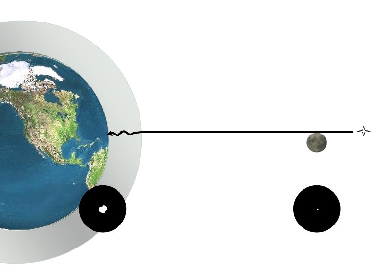
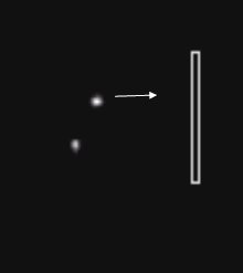
As the Moon (this could also be an asteroid) occults a double
star the following diagram depicts what physically happens
(diagram not to scale):
As the Moon/asteroid moves in front of the system, first it
occults (covers) the first star, resulting in a brightness drop
(called a "step event", but not to zero) then the
second star gets occulted and the brightness of the system goes
to zero.
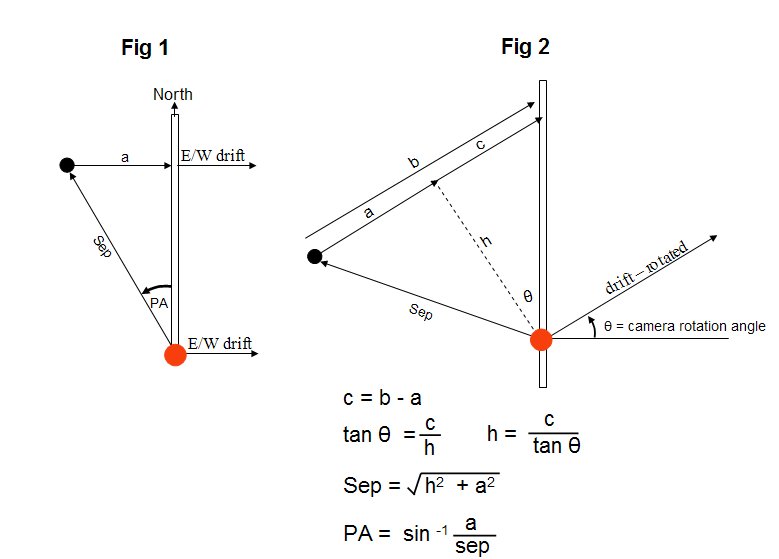
The diagram on the right illustrates position angle PA and
separation of a double star. The red star is assumed
to be the primary (brighter) star.

In the above graph from a lunar occultation the drop in
brightness near video frame #1760 (marked by the arrows) for a
few frames shows a "step event" indicating a double
star. The graph is from an article in Journal of
Double Star Observations Vol 5, No. 4 authored by Dave
Herald and Bob Sandy.
This experimental method uses videos of double star systems
and the video occultation analysis program Limovie to
measure their position angle and separation. Limovie needs
an occultation to measure brightness drops. If we let the double
star system drift though the field of view (FOV) and can
create artificial occultations, then we have data (plots,
contour diagrams) to analyze to compute position angle and
separation.
The Washington Double
Star Catalog (WDS) maintained by the US Naval Observatory has
over 103,000 entries for double/multiple stars. Measurement of
position angle and separation of double stars is of prime
importance in astronomy for the following reasons: 1) position
angle and separation is used to compute orbits of binary stars,
2) with accurate orbits, distances to the binaries can be
computed with good precision, 3) distances to binaries allow the
determination of the absolute physical quantities of the
individual stars (luminosity, mass and sometimes their
diameters), 4) this information is the fundamental basis and
provides the basic calibration for expanding on the distance
scale of stars, clusters, galaxies and the Universe.
Measure of position angle and separation (") of double
stars is needed and can be accomplished by amateurs with CCD
cameras and now using video observations as described below. The
video method will allow the measurement of double star
separations down to about 4"- 5" along with their
position angles.
Artificial
Occultations
INITIAL GOAL: To produce the best possible occulting bar
for video use to create an artificial occultation. By letting the
target star drift past the occulting bar while video recording
it, an artificial occultation occurs.
The only problem in making double star occultation
observations is that we are limited to the Moon (and/or even
rarer asteroid occultation events) to collect data. The Moon's
orbit limits stars in the region ± 5º of the ecliptic. If
we could create an artificial occultation, double stars could be
measured around the entire sky.
With an artificial occultation, keep in mind it occurs inside
the Earth's turbulent atmosphere and this places limitations on
the minimum separation that can be resolved by the video
technique. Outside the Earth's atmosphere with a lunar /asteroid
occultation, the event is usually instantaneous.
Above: Starlight affected by the Earth's constantly moving
atmosphere.
There are two points of focus for a video system:
1) at infinity (such as the Moon/asteroid)
2) at the surface of the video chip itself
We need some sort of occulting bar. Placing a piece of plastic/cardboard at 10 feet (or 100 feet) away from the telescope system is impractical. Placing something at the chip itself seems like a better idea. Several materials were tried and placed at the chip of the Watec 902H camera:
1. piece of plastic
2. piece of tape
3. piece of paper
4. single edge razor blade

CCD
chip on Watec camera. Occulting
bar - piece of plastic Occulting bar - piece of
paper Single edge razor
blade
All of the above attempts proved unworkable. None of the above
occulting bars produced a sharp edge/boundary for creating an
artificial occultation. For one thing, the point of focus
is at the chip itself and it's covered by a transparent plastic
lens approximately 1 mm thick, so none of the above occulting bar
methods could reach a razor sharp focus to create the artificial
occultation. One could remove the plastic lens covering the chip,
but this is also impractical. It's not worth the risk of
scratching or damaging the chip to make the occultation videos.
A
Better Idea
Since the chip on the video camera is the point of perfect
focus, why not use the edge of the chip as the occulting bar ?
By allowing the target star to drift out of the field of view
(FOV) of the chip while video recording, an artificial
occultation is created.
Limovie’s circular apertures could be positioned at the edge of the chip to allow the stars to drift through. With the aperture rings positioned half in and half out of the FOV at the edge of the chip, they can pick up an artificial occultation as the stars moved out of the FOV.
Initial tests results of this method were poor partly due to poor seeing conditions (constantly fluctuating seeing disks) and limitations on the aperture rings.

Above: A double star was allowed to drift off the edge of the video chip FOV. However due to the size of the star's seeing disks, these occultations will be gradual. The primary disappeared over a 35 video frame interval (frames 300-335) and the secondary between frames 385 and 400. This is not a viable method to pin down the exact time of the two occultations.
Two
alternative methods were devised.
1) Peak to Peak measurement. In this method, two Limovie aperture rings were placed in a straight line so that the stars would drift into them and then drift out. This is done in the East-West (EW) direction and the North South (NS) direction. With the Meade LX-200 SCT, the EW and NS push buttons on the Autostar controller were considered to make the system drift using a programmable guiding rate. This is not very scientific but is a start.
Sidereal drift rate (at equator) : 1 second = 15" drift = 0.5"/video frame (at 30 fps).
Sidereal drift rate (dec = 45°) : 1 second = 10.6" drift = 0.35"/video frame (at 30 fps).
Moon’s average drift rate = 0.5"/sec = 0.0167"/video frame (at 30 fps)
If we just use the sidereal drift rates, we have far fewer video frames per arc-second as compared to the Moon, hence the programmable guiding rate on the LX-200’s Autostar seemed an attractive alternative. There are problems with using a telescope's motorized slow motion controls - the motors do not move at a constant rate so there is really no way to determine the exact drift rate in EW or NS.
2) Limovie with rectangular
measurement aperture. Kazuhisa Miyashita (Limovie’s
author) sent me a test version of the program with an
adjustable rectangular measurement aperture for allowing the
stars to drift in/out of. This allowed several types of
artificial occultations to be created and analyzed without
the need to have the stars drift out of the FOV at the edge of
the chip.
Peak to Peak Measurement Tests
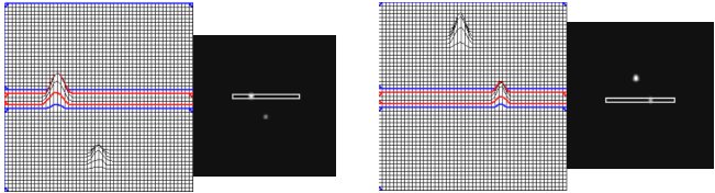
Limovie's circular measurement apertures are used in this method. Two apertures (Object1 and Object2) are aligned and the stars are allowed to drift through. The above diagram shows a left to right (east-west) drift. When the stars drift through the apertures, instead of the light level dropping as in a conventional occultation, the opposite occurs - the light level rises, hence this is an artificial occultation in the reverse manner.
For a double star system, the two stars will drift in and out of two small vertically aligned circular measurement apertures. When the first star drifts through the aperture, brightness is at a maximum. Later the next star will drift through a 2nd aperture creating a 2nd maximum. With use of the 3-D star image contour plots, identification of the video frame of maximums is determined. With GPS time inserted video, the duration of time can be determined and the horizontal separation of the pair. This separation is not the true separation of the pair, but only the "x" component (east-west). To find the separation of the pair, we would need the "y" component of separation (north-south). As stated above using a telescope's North-South motorized slow motion controls would not be an accurate way to do this.
Above: Both stars drift through 2 vertical aperture rings at different times resulting in 2 peaks on the plot. GPS time inserted video allows the duration between peaks and the east-west separation.
Limovie with Rectangular Measurement Aperture
Limovie's author, Kazuhisa Miyashita sent me at my request a test version of Limovie with an adjustable rectangular measurement aperture (from 1 x 1 up to 51 x 51 pixels). This allowed the stars to drift through the skinny rectangle and then drift out causing 2 peaks in the brightness data as in the 2 circular apertures above.

In the above video sequence, Limovie's rectangular aperture is used to allow double star components to drift left to right (east-west). This method is superior to the two circular aperture rings as there is no alignment issue as with the circular apertures.
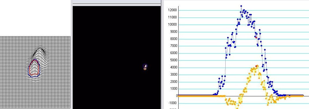
From the diagram below each peak in the 3-D contour diagram will drift through the center of the rectangular aperture. The video frame of which each peak is at the center of the aperture is determined from the data point graph (below right) and by visually looking at the contour diagram (below left). When seeking the video frame of a peak's centroid in the rectangular aperture, determine this visually by moving through the frames one at a time.
In the data point plot below, Limovie's background measurement filter was used to create smooth looking peaks on the graph.
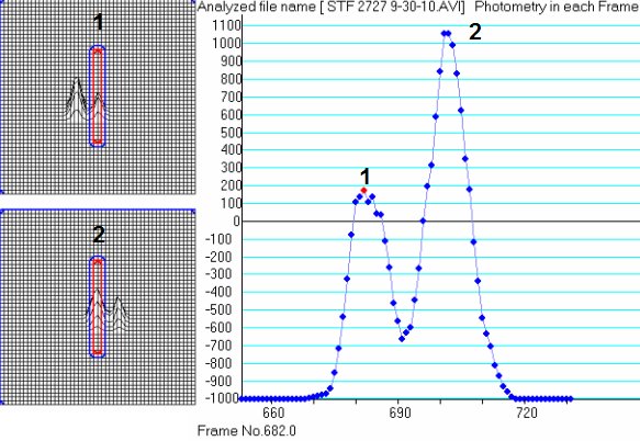
The above diagram aperture shows peak #1 near video frame 682 (secondary, fainter star) and peak #2 near video frame 702 (primary, brighter star). This corresponds to an approximate 10" separation in the east-west direction.
CAUTION: The location of the peaks at the center of the rectangular aperture are not necessarily at the highest points on the plot due to the fluctuating seeing disks of each star.
The rectangular aperture can usually provide results to within 1-3 video frames, which is approximately 0.5"-1.5" at the current drift rate at the celestial equator. The precision is better at declinations further from the equator (cos (DEC) correction applied). To obtain the best results in this technique we need the smallest steadiest star images which in turn makes for skinny contour peaks. This requires a steady atmosphere and excellent optics. Refractors and shorter focal length telescopes in the range of f = 1000-1200mm are preferred. A SCT with a f6.3 focal reducer will give larger FOV's and smaller star images. Too long of a focal length might seem like it will split closer doubles however this will make larger star images which are problematic for determining peaks.
Determining Position Angle and Separation
The drift method provides the east-west component of the separation. We still need a north-south component for determination of position angle and separation. Dave Herald suggested rotating the video camera and let the stars drift through the FOV. In this orientation, the stars would drift on a diagonal across the FOV. With a known camera rotation angle (?) and using Limovie's rectangular aperture we now have enough information to compute absolute quantities of position angle and separation. The method is shown below.
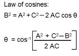
THEORY TO DETERMINE POSITION ANGLE AND SEPARATION:
1. From the triangle below which is located just within the video chip, we need to record the stars drift across the top of the FOV along the line A (east-west) from the points (x,y)1 to (x,y)2 .
Then rotate the camera CLOCKWISE and position the stars near the lower left part of the FOV near point (x,y)3 and allow stars to drift along the entire line C from (x,y)3 to (x,y)2. The points (x,y)1, (x,y)2, (x,y)3 are read directly off Limovie's aperture position readout. With these points known we can compute the sides A, B and C and the camera rotation angle ? using the law of cosines. The drift defined by the side A does not have to be perfectly aligned in the east-west direction but should be as close as you can determine.
The drifts A and C are recorded IN THE SAME VIDEO. After allowing the stars to drift along A, you will need to rotate the camera clockwise and reposition the stars near to the position (x,y)3 and continue recording as the stars approach (x,y)2 . For a typical 15x20 arc-minute FOV the estimated total drifts along A and C will take 3-4 minutes and this is routine recording time for IOTA observers.


Camera attachment for east-west drift
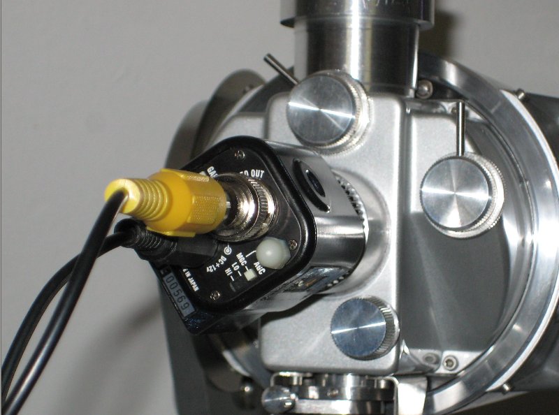

Camera attachment for rotated drift
2. Next we measure the drift duration of the double star components through the rectangular aperture both in the east-west direction (A) and the rotated direction (C). Record the GPS time of each peak when it crosses the center of the aperture from the contour diagrams. Limovie has a frame by frame feature to do this. In practice measure 3 sets of drifts across the FOV and average the results. What's needed is the duration of time it takes for the two peaks to cross the center of the rectangular aperture.
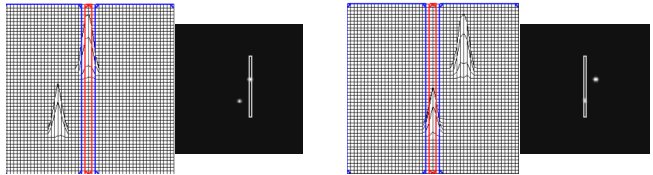
Above: East-west drift of the double star components. Measure the GPS time of each peak as it crosses the center of the rectangular aperture.
Above: Rotated drift of the double star components. Notice the orientation of the double star system has changed. Measure the GPS time of each peak as it crosses the center of the rectangular aperture.
3. The drift quantities in seconds of time are defined in the Figures 1, 2 and 3 below, i.e. "a" and "b".
"a" is the east-west drift duration in seconds of time,
"b" is the rotated drift duration in seconds of time.
? is already determined from Step 1 above.
The skinny rectangles in the Figures are Limovie's rectangular aperture. Then compute the quantities "h", "c", "Sep" and "PA" using the formulas below. Depending upon the orientation of the double stars during the rotated drift, use either the formulas from Fig. 2 or Fig. 3. Choose either a vertical or horizontal rectangular aperture that maximizes the drift times "b".
In each of the figures the red star is the primary (brighter) star and the black star is the secondary (fainter) star. In reality this is not important as the quadrant of the position angle PA will be determined once the primary star has been identified.

4. With the computed separation "Sep" from the above formulas, multiply it by 15 cos(DEC), to convert to arc-seconds (") where DEC is the declination of the star. This cos (DEC) correction is applied to account for the apparent slower sidereal drift rates as you get further away from the celestial equator.
With the PA computed from the above formula, then the correction 180º may have to be applied depending on which quadrant the secondary (fainter) star is.
You have now computed the separation and position angle of the double star.
RESULTS
Here are my results for position angle and separation for the following double stars as compared to the latest entries in the Washington Double Star Catalog (WDS). A Watec 902H Ultimate camera and a 90mm (3.5-inch) Questar was used. The observations were made in a subdivision from a school parking lot.
| Double Star |
Limovie Separation(") |
WDS Separation(") |
Limovie Position angle |
WDS Position angle |
| 61 Cygni |
29.5 |
31.1 |
152.2 |
152 |
| STF 2280 |
14.7 |
14.2 |
195 |
183 |
| 15 AQL |
42.2 |
40.5 |
212 |
209 |
| STF 2264 |
6.1 |
6.3 |
252 |
256 |
| STF 2379 |
12.9 |
12.6 |
121.6 |
121 |
| STF 2848 |
10.2 |
10.8 |
57.6 |
56 |
| STF 2978 |
7.7 |
8.4 |
143 |
145 |
Discussion
1) This artificial occultation video method works best with excellent seeing conditions and shorter focal length telescopes. The separations results for 61 Cygni and 15 AQL differ by 1.6" from the WDS. This is likely due to the fact that these systems are brighter and have larger seeing disks or it could be a random effect. Alternatively, the gain control of the video camera can be turned down making the recorded star images smaller covering fewer pixels.
2) The fluctuating stars due to seeing conditions can produce multiple brightness peaks in the graphs. The highest peak on the graph doesn't necessarily produce the correct video frame where the star is centered in the rectangular aperture. Only visual examination of the 3-D contour plots can help identify the correct location of the peak at the center of the measurement aperture and hence that corresponding video frame.

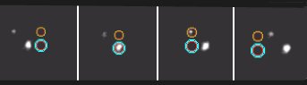
100 frame 3-D contour map sequence. The constantly changing atmosphere affects the seeing disks.
3) Limovie's rectangular aperture produces cleaner looking plots than the circular aperture rings. The rectangular aperture also eliminates the alignment issue when placing the two circular aperture rings in a straight line. Use a small aperture 3-5 pixels wide. Too large an aperture will make it difficult to locate the peak's center location, and apertures below a 3 pixel width won't allow you to resolve the aperture.
4) Accuracy: I have found that the visual examination of the 3-D contour plots on a frame by frame basis produces the more accurate video frame of the peak centered position within the rectangular aperture. By making at least 3 sets of measurements for each east-west and rotated drift this helps reduce the chance of a spurious result from a spike in the fluctuation of the stars seeing disks.
5) Focus. The focus of the double stars is critical and you need to have the best possible focus. If you cannot see the two stars resolved on the video, then Limovie will not be able to resolve them either. With very close doubles, it may be necessary to focus on another star field and then bring the telescope back to the double star. When rotating the camera it possible that the focus will change. This will depend on the screw threads of your adapter. The best way to determine this is to do it and see. I have not seen this problem in a 1/4 turn of the camera.
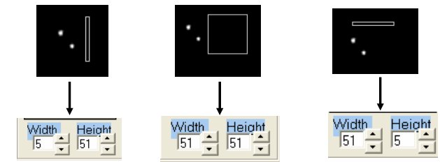
TIPS
Limovie's rectangular aperture is adjustable as follows:
Determining (x,y)1, (x,y)2, (x,y)3
These 3 points are found using Limovie's (x,y) position readout as shown in the screen shot below:
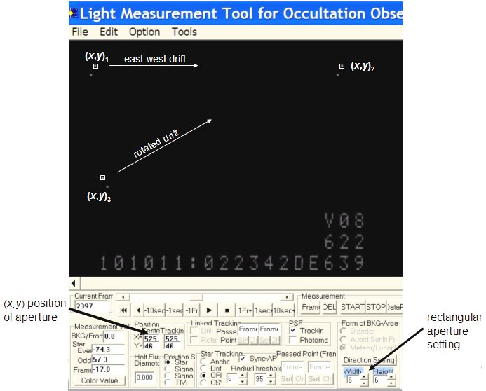
By positioning the aperture (5 x 5 pixel size) at the point where one of the double stars will drift over, this gives (x,y)1, (x,y)2 and (x,y)3. The point (x,y)2 is where the east-west and rotated drifts intersect. It will take some trial and error in positioning it so that both drifts pass over this point. For (x,y)1 and (x,y)3 place the aperture at points on the left side of the video frame to complete the triangle ABC. The length of the triangle sides ABC are computed from the differences in their (x,y) coordinates using the Pythagorean theorem distance formula.
Please send your comments, suggestions for improving on this technique to me.
Richard Nugent
Executive Secretary
International Occultation Timing Association