|
|
|
|
|
|
| |
|
All times UT unless otherwise noted |
|
COOL VEST by Tom Campbell |
|
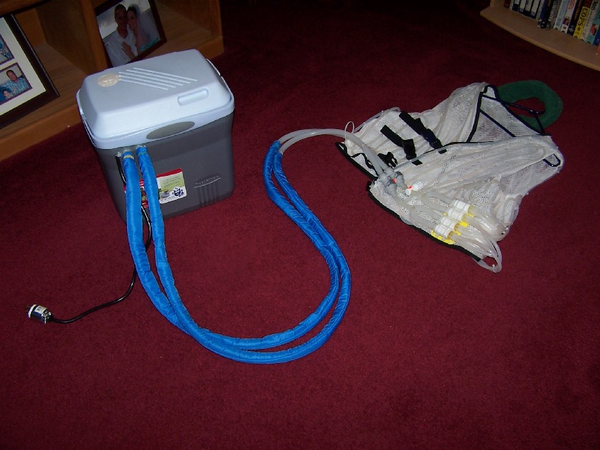
Overview: This build it yourself design cooling vest is to reduce heat stress and fatigue on observers during the hottest of the summer nights when both the air temperature and dew point temperatures are very high. Particularly when observing in parts of the USA, Australia and other parts of the world when hot nights at the telescope can feel very oppressive. The vest cost me just over $100.00 in materials and a total of 20 hours of my personal labor. Commercial water cooled vests cost from $400.00 and up.
Figure 1.
Figure 2.
|
|
Background: This cooling vest is the final product after a year of experimenting with two types of pumps and two types of tubing material. The vest has three cooling partitions each with their own separate water tubing. That is the left front, the back and the right panel. The original design had a single 3/16" I.D. silicone tube run for each of the three panels, but it didn't quite provide enough cooling for me. I then tried using 5/16" I.D. latex gum rubber tubing (surgical tubing) that did increase the total cooling water flow rate. But it had larger wall thickness, natural rubber is a better thermal insulator and the net cooling effect was less than the original 3/16" O.D. silicone rubber tubing. I tried using a 12 volt automotive windshield washer pump which had more pressure but it had a noisy sound as well as a serious RFI problem not to mention more power consumption. Besides this type of pump was never intended for continuous use and its long term reliability was questionable. The 9 watt AC powered submersible magnetic drive aquarium pump proved to be quietest sound as well as no RFI emissions and is designed to run indefinitely. My final solution was to double the number of silicone rubber tubes on the vest since that material conducts heat better than natural rubber does. Now there are a set of two tubing runs on each of the three vest panels. The second set of tubing runs between the tubes of the first set in an "interlaced pattern". This increased the vest water flow rate from 18.75 GPH to 37.5 GPH which is adequate for this cooling vest system.
|
|
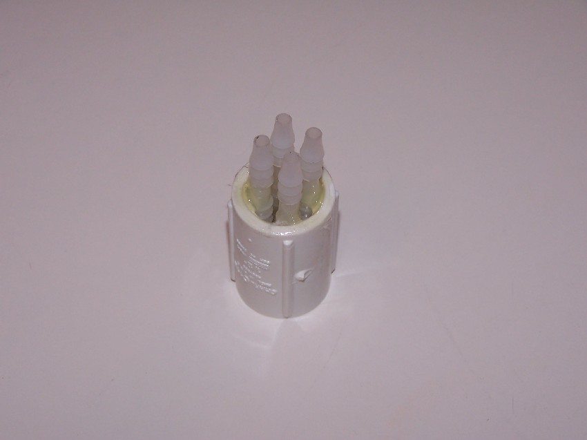
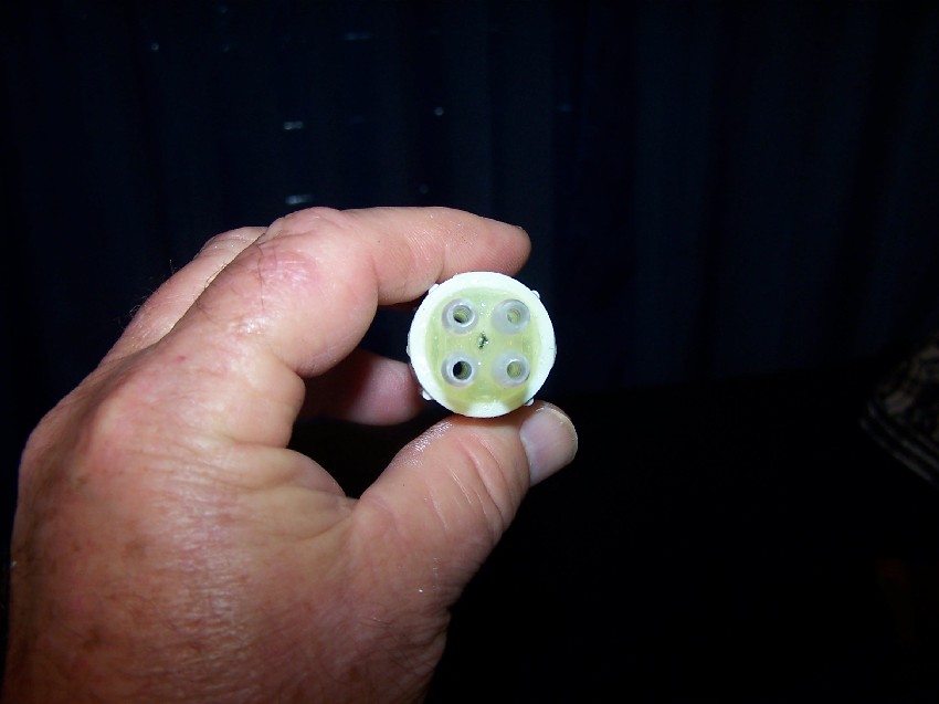
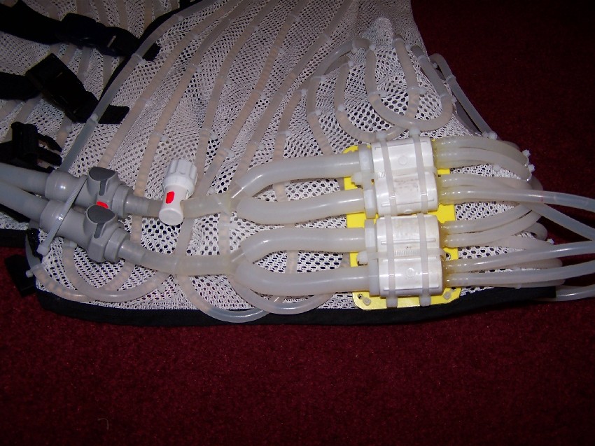
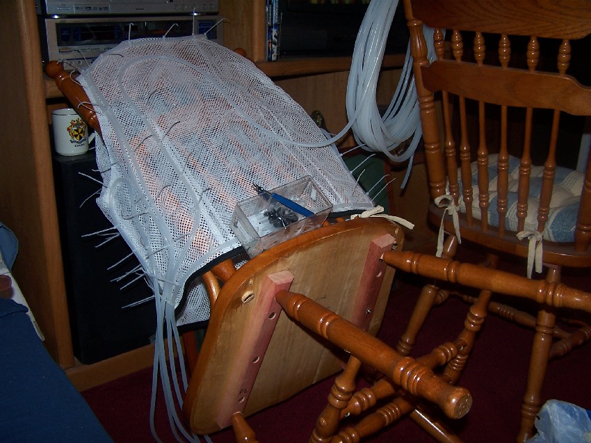
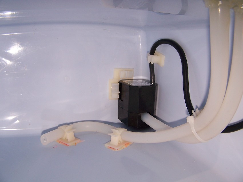
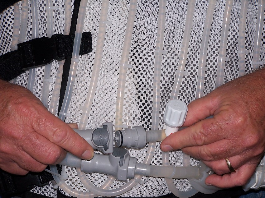
Construction: 1) Making the vest: The open mesh material (see parts list at end of article) should have at least 1/8" holes and be non stretchable. This is the key framework for the support of the silicone rubber tubing that will be fastened to it using 4" plastic cable ties. If you don't have anyone in your family, relatives, friends, etc. who knows how to sew you may have to go to a professional tailor to have it made. If you can have it cut to fit your body it will feel cooler. However I recommend it fit a little loose and use adjustable straps sewn into it so you can snug it up as you are putting it on. After the tubes are fastened to it they become an integral part of the structure of the vest making it feel like a heavy winter vest especially when its tubes are primed with water. 2) After the basic open mesh vest is made I recommend constructing the water manifold assembly and attach it to the vest before installing the cooling tubing to the vest. This gives you a start and stop point and barbs to anchor each of the 3/16" tubing and to reduce waste trimmings of the tubes later. (The first experiment I ran the tubing putting the manifold on last and had about an excess foot on each tube to trim off---a costly waste). 3) Constructing the 4 water manifold sub assemblies: Aside from the sewing of the vest material itself, this is the most time consuming. It is not hard.....just have a lot of patience. There are no commercially off the shelf inline 3/8" barb to four 3/16" barb manifolds that I know of. So each of these four manifolds has to be hand made. But once these sub assemblies are finished the remainder of the cooling vest construction is easy. A). For each of the four inline water manifolds (refer to the parts list) you will need the following: 1 3/8" hose barb to 1/2" threaded male threaded adapter 1 PVC 1/2" threaded female to female coupler 4 3/16" to 3/16" barb hose splicer 1 roll of 1/2" Teflon pipe sealing tape 1 tube of two part quick set (5 minute) epoxy glue 1 tube of two part extended time (60 minutes) epoxy glue
Figure A
Figure B
Figure C
Figure D
Figure E
Figure F
Figure G
Figure 6.
Figure 3.
Figure 9.
Figure 4.
Figure 5.
Figure 2.
|
|
Operating
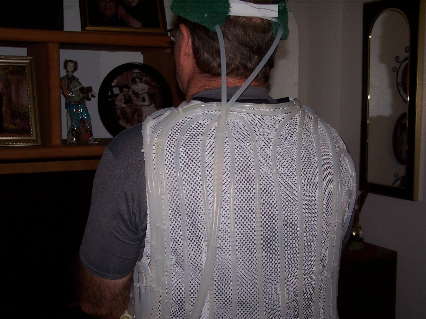
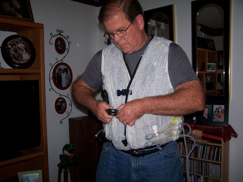
instructions: 1) Priming the system: Before wearing the vest hook its tubing quick disconnect inserts to the cooler's two umbilical mating hose couplers. The water supply connectors are marked with red dots. Fill the cooler with crushed ice and only enough water to cover the intake of the pump. Make sure the vest, the umbilical hoses and the ice bucket are nearly the same level. Power on the pump and if you see air bubbles in the water supply line add a little more water to cover the pump and the supply line air bubbles disappear. Now look at all of the smaller tubes on the vest and initially you may notice some air bubbles moving in them. Keep the pump running until you no longer see bubbles in any of the vest tubing and touch each tube to see if they are all cool. After this system priming procedure is completed a siphon is established allowing the water flow rate to be the same regardless if the ice bucket is higher or lower than the vest. Detach the water umbilical lines using their non leak disconnects now that the system water prime has been established. 2) Donning the vest: First a snug fitting stretch polyester tee shirt is recommended underneath the vest to keep the cold tubes from direct contact with the body. Next you put on the cooling vest and tighten the 3 front straps so it fits snugly on your body (link to figure 7). Next pass the umbilical tubes through the 3 large tie wrap loops on the bottom right of the vest and mate the quick disconnect couplers (Link to figure 8). Power on the pump if it is not already running. If you are using the optional head and neck coolers put them on making sure their tubes have enough slack for mobility of the neck and head. If not using the optional head or neck cooler (link to Figure 9) their water supply and return port barbs must be capped. Worn over the cooling vest is an insulated and water proof winter vest (link to figure 10), or a winter jacket with its sleeves cutoff. This outer garment improves the efficiency of the cooling system by preventing ambient heat from being absorbed by the tubes as well as reducing the absorption of the heat of water condensation on the tubes. 3) Manual flow rate control: If after a while of sitting still and you begin to feel chilled simply turn the needle pinch control valve (link to Figure 8) to reduce the water flow rate to your desired level of cooling comfort. This takes several minutes before any difference is felt. If you want quicker action turn off the pump or disconnect one of the lines for a few minutes after making a needle valve adjustment and then start the water circulating again. 4) Mobility: There is about a 12 foot diameter circle, with the ice bucket in the center, that the cooling umbilical tubes will allow. To move further simply pickup the cooler with one hand and you can move as far as the extension cord will allow.
Figure 7.
Figure 8.
|
|
List of
Materials 3 Yds Open Mesh Fabric JoAnn Fabric Polyester or Nylon Drape Materials Dept. 1 Ea Vest Pattern Wal-Mart McCall's #8285-H Exact # depends on body size AR Misc Bias tape, one inch belt material, plastic buckles, 4" and 8" cable tie wraps, etc. 100 Ft 3/16" I.D. Silicone Tubing U.S. Plastics 54032 1/16" wall thickness (5/16" O.D.) 18 Ft 3/8" I.D. Silicone Tubing U.S. Plastics 54037 1/8" wall thickness (5/8" O.D.) 1 Ft 3/8" I.D. Silicone Tubing U.S. Plastics 54036 1/16" wall thickness (1/2" O.D.) 2 Ea 3/8" Shutoff coupling body U.S. Plastics 60688 2 Ea 3/8" Shutoff coupling insert U.S. Plastics 60813 1 Ea Flow control pinch valve U.S. Plastics 64062 Fits 1/2" O.D. of P/N 54036 2 Ea 3/8" "Y" hose barb U.S. Plastics 64016 1 Ea Danner Mag-Drive pump Marine Depot DN115 Danner model# 1.5, 140 GPH 1 Ea 20 Quart ice chest Wal-Mart Rubbermaid or equiv. 4 Ea 1/2" Female PVC coupler Ace Hardware Both ends 1/2" female pipe thread 4 Ea 3/8" barb to 1/2" Male ADPT. Ace Hardware PL-328 Hose barb to male thread adapter 16 Ea 3/16" X 3/16" barb splicer Ace Hardware PL-101 Nylon 3/16" hose splicer Links to Vendors: http://www.usplastic.com/catalog/default.asp http://www.marinedepot.com/ps_AquariumPage~PageAlias~powerheads_pumps_danner_mag_drive_supreme.html
Figure 10.
|
![]()
This site was last updated 08/10/16
© Copyright, Derek C Breit. All rights reserved.